Computer Networks
Computer networks study how multiple computing entities exchange information, share resources, and compose into larger systems. The subject is not primarily about how cables are physically connected, but about the mechanisms that make distributed computation possible: protocols, addressing, routing, congestion control, reliability, and layered abstraction.
Why It Belongs to Computer Science
Computer networks belong to computer science because their core question is: how do multiple computational systems communicate so that they can behave like a larger computational system? Protocols can be understood as state machines and rule systems, routing is a graph and optimization problem, congestion control involves feedback and resource allocation, and reliable transport involves ordering, consistency, and error recovery. These are not merely wiring issues; they are classic questions about computation and system behavior.
Networks obviously overlap with computer engineering, especially at the physical layer, link layer, switching hardware, and NIC design. But in the main curricular sense, the field is primarily about communication rules and distributed system behavior, so it fits more naturally under Computer Science.
Ch.1 Internetworking
1.1 The Internet
In the beginning, a computer was a standalone machine. People would input information into this isolated machine, and it would compute and produce a result. As technology advanced, people began connecting multiple computers together, forming computer networks.
Initially, computers were only connected within a small area, creating a local area network (LAN). Ethernet is a technology for implementing LANs that connects different computers via network cables.
As demand grew, computers around the world eventually became interconnected, forming the Internet — the network of networks, a vast global networking system. To achieve efficient internetwork communication, the following concepts are essential:
- TCP/IP Protocol: The protocol for sending and receiving information over the Internet, and the primary subject of most computer networking courses. We will cover this in detail later.
- ISP (Internet Service Provider): Organizations that provide access to the Internet.
Let us see how TCP/IP and ISPs make the Internet work:
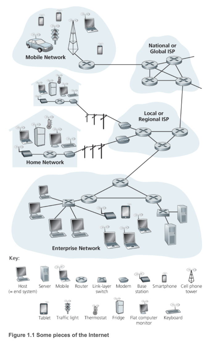
In the diagram above, we can see several additional terms:
- Packet: Information sent by a computer is divided into small chunks called packets, the basic unit of network transmission.
- Communication Link: The medium through which network transmission occurs, such as optical fiber or radio.
- Router: A device that connects heterogeneous networks — that is, different types of networks — performing optimal path selection to forward packets from one network to another.
- End System / Host: Located at the network edge, end systems are the consumers and producers of information. Smartphones, laptops, web servers, and similar devices are all end systems.
1.2 TCP/IP Protocol
A protocol is a set of communication rules. As mentioned above, the packet is the smallest unit transmitted in a computer network, and it is composed of bits — binary numbers. Regardless of the physical medium, we can only transmit binary data: optical fiber converts binary into light pulses, wireless transmission converts it into radio frequency or phase shifts, and copper wire converts it into corresponding voltage and current patterns.
Clearly, a packet is not the content we originally intended to transmit. For instance, if you want to send a message to a friend, you neither can nor need to send raw binary data — the computer handles that. The information you want to send is called a message. Obviously, messages vary greatly depending on the context: a website sends you a web page, you send your friend an email, and so forth. The specific message content depends on the application, so the message belongs to the application layer.
TCP/IP is currently the most widely used Internet protocol suite. It defines the application layer and other layers as follows:
- Application Layer: You create a message.
- Transport Layer: The message is divided into segments, with port numbers added to ensure data reaches the correct application.
- Internet Layer: Segments are encapsulated into packets, with IP addresses added to ensure data reaches the correct host.
- Link Layer: Packets are encapsulated into frames, with MAC addresses added to ensure data reaches the next-hop device. Frames are then converted into binary electrical signals or optical signals for transmission.
Note that in the classic textbook Computer Networking: A Top-Down Approach, the Internet layer is called the Network layer, and the Link layer is further divided into a Link layer and a Physical layer. Since TCP/IP is used almost universally in practice, these notes follow the four-layer TCP/IP model by default.
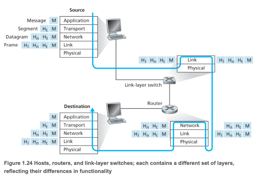
The diagram above illustrates the layered working mechanism of the TCP/IP protocol.
A protocol defines the format and order of messages exchanged between two or more communicating entities, as well as the actions taken upon sending and/or receiving a message or other events.
The three essential elements of a protocol:
- Syntax: Each segment of content conforms to a specific format — for example, the first 8 bits of a message might be the source address and the next 8 bits the destination address (this is just an illustration, not literal).
- Semantics: Each segment of content must convey a specific meaning — for example, what actual address the binary in the source address field refers to.
- Timing: The communication process — the execution order of each task.
1.3 Local Area Networks
Now that we have a general idea of what the Internet looks like, let us examine how end devices connect to it.
We can see that there are mainly two types of devices in a network: terminals that provide and consume services, and Internet infrastructure that enables transmission. An access network is the physical network that connects end systems (your computer, phone, etc.) to the first router of the Internet Service Provider (ISP). It is the last mile for a user to reach the Internet, enabling end users to physically connect to the global Internet.
The device that implements this access network step is the edge router. You can think of it as the gateway to the Internet, serving as the network's entry point or gateway, responsible for connecting your local network to the broader wide area network (WAN) or Internet core. It is the endpoint of the access network and the starting point of the ISP network. It aggregates users from the LAN into the WAN.
Today, virtually every entry point is connected to a LAN. In most homes and schools, LANs and Wi-Fi are used to connect local devices to the edge router.
Most companies today host their services on cloud providers' servers, such as AWS, GCP, and Alibaba Cloud. These cloud computing companies provide superior distributed network infrastructure, freeing service providers from spending effort on network optimization. Through the cloud provider's network virtualization technology, each customer has a logically isolated private network space (VPC) — similar in concept to a home LAN, though implemented differently. This VPC connects to the public Internet securely through the cloud provider's edge routers and gateways.
A gateway is the entry and exit point between two different networks. As mentioned above, the Internet and the LAN are connected via an edge router — the edge router is that door. The gateway is each specific door. In other words, devices within a LAN communicate with each other without going through the gateway; however, when a device on the LAN needs to interact with content on the Internet, it must go through the gateway.
For ordinary users, there is no need to worry about gateway configuration — the edge router handles it automatically. A gateway is a logical entry/exit point, represented as an IP address that can forward packets to their destination. It is also a device address used to determine the next-hop forwarding target for a packet.
In summary, access network, edge router, and gateway are different ways of expressing the same concept of terminal-to-Internet communication:
- LAN: A neighborhood — responsible for local communication within a local scope, isolated from the Internet.
- Access Network: The private driveway within the neighborhood — the physical pathway from the local network to the Internet.
- Edge Router: The neighborhood gate — hardware that performs routing and forwarding tasks.
- Gateway: The neighborhood gate — includes the default gateway IP (the address sign on the gate) and routing functionality (the gate guard who tells you where to go next based on the destination IP).
When we transmit a message, the process is essentially as follows:
- The message is split into multiple packets, each encapsulated in a large envelope (frame).
- The terminal places the packet in a large envelope with the default gateway's MAC address — the physical address of the neighborhood gate.
- The terminal sends the frame to the default gateway IP (i.e., the edge router) — analogous to driving to the neighborhood gate.
- The gateway discards the LAN-specific frame, examines the packet's destination, and creates a new frame containing the next-hop router's MAC address — like the gate guard reading your destination and telling you where to go next.
- The envelope enters the Internet — onto the public roads (ISP).
We can see that a frame does not directly record the final destination during transmission; instead, it records the next hop. At each router, the next-hop address is updated based on the final destination IP recorded in the packet, progressing hop by hop toward the final destination gateway. In other words:
- The packet records the final destination IP address — analogous to the recipient's home address.
- The frame only records the next-hop address.
Specific routing algorithms and related topics will be covered in the link layer section.
1.4 ISP
Once the envelope (frame) enters the Internet, most of the infrastructure is now provided and maintained by ISPs. Today, some large network service providers, such as Google, also lay their own infrastructure like private undersea fiber optic cables, effectively acting as ISPs. However, when we discuss ISPs in general, we refer to traditional ISPs, including:
- Tier-1 ISP: At the top of the Internet backbone, these own massive global networks and form the core of the Internet. Major companies include AT&T, Verizon, NTT, and Telia Carrier.
- Tier-2 ISP: Also called regional ISPs, they handle regional or national coverage, connecting the Tier-1 backbone to broader areas. They pay Tier-1 ISPs for transit but can also sell services to local ISPs.
- Tier-3 ISP: Also called access ISPs, they primarily sell Internet access directly to end users. They are the builders and maintainers of the last mile.
With the evolution of the Internet, the three-tier ISP classification and company roles have become quite blurred. For example, China's three major telecom operators simultaneously provide Tier-1 through Tier-3 ISP services.
1.5 Delay
Now we know that a message goes through the following steps during transmission:
- Packaged into an envelope
- Transmitted across the Internet
- The receiver opens the envelope
Each step takes time. Let us break it down:
- Time for the sender to package the envelope — involves processing delay.
- Time for the sender to transmit the envelope to the edge router — involves transmission delay and propagation delay.
- Time for the envelope to travel from the sender's edge router to the receiver's edge router — involves processing, queuing, transmission, and propagation delay.
- Time for the receiver to retrieve the envelope from the edge router to the end device — involves transmission delay and propagation delay.
- Time for the receiver to open the envelope — involves processing delay.
Among these, queuing delay is the time a packet waits in the router's buffer before being sent to the communication link — this is variable. The others are fixed:
- Transmission Delay: \(T_{\text{trans}} = \frac{L}{R}\), where L is the packet length and R is the transmission rate (bandwidth).
- Propagation Delay: \(T_{\text{prop}} = \frac{d}{s}\), where d is the link length and s is the signal propagation speed.
- Processing Delay: Typically very short, on the order of milliseconds.
Total delay refers to the total time elapsed from the moment a packet is pushed onto the communication link by the sending host until all its bits arrive at the receiving host:
The most significant contributors are propagation delay and queuing delay. Propagation delay is the time required for signals to travel through the physical medium, while queuing delay is the time spent waiting in the queue at each router along the path.
The ping value commonly used in speed tests is approximately:
Transmission delay and processing delay are usually negligibly small. Generally speaking, a consistently high ping is mainly caused by the target host being far away, dominated by propagation delay; whereas wildly fluctuating ping values are mainly caused by network congestion, dominated by queuing delay.
The packet loss that many gamers experience during online gaming mostly occurs during queuing. Each output port of a router has a finite-sized buffer or queue. When the rate of arriving packets consistently exceeds the link's transmission rate, the queue fills up. Any newly arriving packet cannot enter the queue, and the router has no choice but to drop it. Of course, packet loss can occur at other stages as well, but most of it happens during queuing.
We define traffic intensity as:
where L is the packet length, a is the average packet arrival rate (the rate at which the router receives packets), and R is the link bandwidth (the router's capacity to send packets).
\(L \times a\) equates to:
So the overall formula is:
When I approaches 0, demand is far less than capacity, the queue is almost always empty, and queuing delay tends toward 0. When I is between 0 and 1, this represents a normal load — demand is less than capacity but there is contention; overall, the router can handle all the traffic. When I exceeds 1, demand exceeds capacity, the queue exceeds the router's capacity limit, and new packets are dropped, resulting in packet loss.
The transmission throughput from end system A to end system B is determined by the bottleneck link along the entire transmission path:
That is, the end-to-end throughput of a connection is determined by the transmission rate of the slowest link on the path. This is one of the most fundamental and important principles in computer networking: the performance of an entire system is always determined by its weakest component.
Ch.2 Application Layer
2.1 Web
The application layer of computer networks is the highest layer in the TCP/IP protocol suite. It directly serves user applications and provides network services. Application layer protocols define how applications communicate with each other and how users interact with the network. It contains a large number of protocols supporting various user applications.
Web services are among the most frequently used services in daily life, enabling communication between browsers and web servers. They are primarily based on HTTP/HTTPS (Hypertext Transfer Protocol):
- HTTP (Hypertext Transfer Protocol) is the standard protocol for transferring hypertext files (HTML files), images, videos, and other resources between web clients (typically browsers) and web servers.
- HTTPS adds encryption via SSL/TLS (Secure Sockets Layer / Transport Layer Security) on top of HTTP. Its purpose is to ensure the security, integrity, and privacy of data transmitted between users and servers.
HTTP uses TCP port 80 by default, and HTTPS uses TCP port 443 by default.
A TCP port is a logical identifier used to distinguish different applications or services on the same computer. Imagine you have a building (this building is your IP address), with many different offices inside (these offices are your applications or services).
- IP address: Used to find the correct building (i.e., a specific host on the network).
- Port number: Used to find the correct office within the building (i.e., a specific application on the host).
TCP port numbers are 16-bit numbers ranging from 0 to 65535. When a data packet (called a segment at the transport layer) arrives at a host, the operating system examines the destination port number of the segment and delivers the data to the application listening on that port.
Common well-known TCP ports (0–1023, permanently assigned to specific network services by IANA) include:
| Port | Protocol/Service | Application |
|---|---|---|
| 21 | FTP | File Transfer Protocol (control connection) |
| 22 | SSH | Secure Shell Protocol |
| 23 | Telnet | Remote terminal service (insecure) |
| 25 | SMTP | Simple Mail Transfer Protocol |
| 53 | DNS | Domain Name System (uses both TCP/UDP) |
| 80 | HTTP | Hypertext Transfer Protocol (plaintext) |
| 443 | HTTPS | Secure Hypertext Transfer Protocol |
A TCP connection is uniquely identified by a four-tuple:
For example, when your browser (client) accesses a website (server):
- Server: Listening on
1.2.3.4:443 - Client: Temporarily assigned a dynamic port, e.g.,
192.168.1.100:50000
When data arrives at server 1.2.3.4, the operating system sees that the destination port is 443 and knows to deliver the data to the web server program. Meanwhile, the server can also distinguish which client sent the data via the source port number 50000.
2.2 Email
Email services rely on three main cooperating protocols to send, receive, and manage mail:
| Protocol | Port (TCP) | Function | Service Model |
|---|---|---|---|
| SMTP | 25 / 465 / 587 | Sending: Pushes mail from the sender to the recipient's mail server. | Push |
| POP3 | 110 / 995 | Receiving: Allows the client to download mail from the server to local storage. | Offline management |
| IMAP | 143 / 993 | Receiving/Managing: Allows the client to synchronize and manage mail on the server. | Online synchronization |
SMTP (Simple Mail Transfer Protocol) is primarily responsible for mail delivery. When a user sends an email, the mail client pushes the message to the sender's mail server, which then uses DNS to look up the recipient's server address and forwards the mail using SMTP.
To receive mail, users need POP3 or IMAP. POP3 tends to download mail to the local device and delete the copy on the server, enabling offline operation. IMAP, on the other hand, allows users to keep mail on the server for convenient multi-device state synchronization (e.g., read/unread status, folder structure).
2.3 FTP
FTP (File Transfer Protocol) is a standard protocol for transferring files between a client and a server.
FTP's most distinctive feature is its use of two separate TCP connections:
- Control Connection: Uses TCP port 21. It transmits control commands (such as login, directory changes, upload/download requests). This connection is persistent throughout the session.
- Data Connection: Used for the actual file data transfer. This connection is closed after each file transfer completes.
There are two modes for establishing the data connection:
- Active FTP: The client sends its port number, and the server actively connects to the client's specified port using port 20.
- Passive FTP: The client sends a request, the server replies with a random port number it has opened, and the client actively connects to that random port. Passive mode is more common because it traverses firewalls more easily.
2.4 SSH
SSH (Secure Shell) is a protocol that provides encrypted network services for securely accessing remote computers. SSH was designed to replace insecure protocols such as Telnet and FTP. It encrypts all data during communication (including login credentials and commands), ensuring the confidentiality and integrity of data transmission.
The most common uses of SSH are:
- Remote command-line login: Users connect to remote servers through a terminal and securely execute commands.
- Secure file transfer: e.g., SFTP (SSH File Transfer Protocol), which performs file transfers over a secure SSH connection.
- Port forwarding / tunneling: Encapsulating insecure network traffic within an SSH encrypted channel for transmission.
2.5 DNS
DNS (Domain Name System) is the Internet's "phone book," responsible for resolving human-readable domain names into IP addresses.
DNS is not centralized but distributed across millions of servers worldwide, forming a hierarchical tree structure:
- Root DNS Servers: At the top level, storing information about all top-level domains.
- TLD DNS Servers (Top-Level Domain): Responsible for top-level domains such as
.com,.org,.cn, etc. - Authoritative DNS Servers: Storing the IP address records for specific domain names (e.g., the IP address of
google.com).
DNS queries primarily use UDP port 53 for speed. When a user enters a domain name, the client performs a recursive query or iterative query through a local DNS server (provided by the ISP), ultimately obtaining the IP address from the authoritative server. Caching plays a crucial role in the resolution process, significantly speeding up subsequent queries.
2.6 P2P
The P2P (Peer-to-Peer) model differs from the traditional client/server model — it is a distributed application architecture. In a P2P architecture, communicating devices (nodes or peers) simultaneously act as both clients and servers. Each peer can communicate directly with other peers, sharing resources and services. Resources and processing power are distributed across the network, without reliance on a single central server.
P2P applications are widespread:
- File sharing: e.g., BitTorrent, where users simultaneously download files from multiple sources and upload portions they already have to other users.
- Distributed computing: e.g., certain cryptocurrencies (Bitcoin), where nodes collectively maintain the ledger.
- VoIP (Voice over IP): Some VoIP applications use P2P technology to establish call connections.
2.7 Socket API
The Socket API is an abstraction of a communication endpoint in network communication. You can think of it as a "door" or "handle" through which an application communicates with the network protocol stack. An API (Application Programming Interface) is a set of functions that programmers can call to achieve specific functionality. The Socket API is a standardized interface (function library) provided by the operating system for programmers to create, manage, and use sockets for network communication.
Through the Socket API, applications can perform the following core operations:
| Operation | Function Example (C/C++) | Description |
|---|---|---|
| Create | socket() |
Create a new socket. |
| Bind | bind() |
Bind the socket to a local IP address and port number. |
| Listen | listen() |
Server-side: listen for incoming connection requests. |
| Connect | connect() |
Client-side: initiate a connection request to the server. |
| Send/Receive | send(), recv() |
Send and receive data over the network. |
| Close | close() |
Close the socket and terminate communication. |
The Socket API is not a protocol itself — it is the tool that enables application layer protocols to be implemented. All the application layer protocols mentioned earlier (HTTP, SMTP, FTP, etc.) are implemented by applications.
- A browser implements HTTP client functionality.
- A web server implements HTTP server functionality.
- An email client implements POP3/IMAP/SMTP client functionality.
When these applications implement their respective protocol logic, they all rely on calling the Socket API to perform the actual network data transmission.
For example:
| Protocol Example | Implementation |
|---|---|
| HTTP | The web browser calls socket() to create a socket, then calls connect() to connect to the web server's port 80, and then calls send() to send the HTTP request message. |
| DNS | The DNS resolver calls socket() to create a socket, typically using UDP, then calls sendto() to send a query message to the DNS server's port 53. |
Application layer protocol designers and implementers need not concern themselves with how data is segmented, routed, or sent through the network interface card.
- Socket API upward: Provides a clean interface that allows application layer programs to easily send and receive data without understanding the complex underlying network details.
- Socket API downward: Hands off the application layer data to the transport layer (TCP/UDP) for processing and transmission.
Socket Programming
A socket is like a port or connection point through which programs communicate over a network. It provides applications with a standard, portable way to send and receive data, whether between different processes on the same machine or between processes on two different machines connected via the Internet. It is typically based on standard network protocols such as TCP (Transmission Control Protocol) or UDP (User Datagram Protocol).
The most common application pattern for socket programming is the Client-Server model.
In this model, the server waits for and accepts client connection requests, then processes data:
| Step | Operation | Description |
|---|---|---|
| 1. | socket() |
Create a socket: Specify the protocol family (e.g., IPv4) and type (e.g., TCP). |
| 2. | bind() |
Bind address and port: Bind the socket to a local IP address and port number. This is the "address" clients connect to. |
| 3. | listen() |
Listen for connections: The server socket enters a listening state, ready to accept client connection requests. |
| 4. | accept() |
Accept a connection: Block and wait until a client attempts to connect. Once accepted, a new socket is created dedicated to communicating with this client. |
| 5. | recv()/send() |
Communicate: Receive and send data through the new socket. |
| 6. | close() |
Close: Close the socket after communication ends. |
The client actively initiates a connection request and communicates with the server:
| Step | Operation | Description |
|---|---|---|
| 1. | socket() |
Create a socket: Use the same protocol family and type as the server. |
| 2. | connect() |
Connect to server: Initiate a connection request using the server's IP address and port number. |
| 3. | send()/recv() |
Communicate: Send and receive data through this socket after a successful connection. |
| 4. | close() |
Close: Close the socket after communication ends. |
Below is a Python TCP Echo server example that demonstrates how to use Python's socket module to implement a server that receives any message from a client and returns it as-is ("echo").
Server-side code (server.py)
import socket

# 1. 配置
HOST = '127.0.0.1'  # 标准回环地址 (本机)
PORT = 65432        # 要监听的端口

# 使用 with 语句,确保 Socket 会被自动关闭
with socket.socket(socket.AF_INET, socket.SOCK_STREAM) as s:
    # socket.AF_INET 表示使用 IPv4
    # socket.SOCK_STREAM 表示使用 TCP 协议 (流式套接字)

    # 2. 绑定地址
    s.bind((HOST, PORT))
    print(f"服务器已启动,监听 {HOST}:{PORT}...")

    # 3. 监听连接
    s.listen()

    # 4. 接受连接(阻塞等待客户端连接)
    # conn 是新的连接 Socket,addr 是客户端的地址
    conn, addr = s.accept()
    with conn:
        print(f"连接来自 {addr}")

        # 5. 通信循环
        while True:
            # 接收数据,最多接收 1024 字节
            data = conn.recv(1024)
            if not data:
                # 客户端断开连接
                break

            # 将收到的数据原样发送回去 (Echo)
            conn.sendall(data)
            print(f"回送数据: {data.decode('utf-8')}")

    print("连接关闭。")
Client-side code (client.py)
import socket

# 1. 配置
HOST = '127.0.0.1'  # 服务器的地址
PORT = 65432        # 服务器的端口

MESSAGE = "Hello, Socket Programming!"

# 使用 with 语句,确保 Socket 会被自动关闭
with socket.socket(socket.AF_INET, socket.SOCK_STREAM) as s:

    # 2. 连接服务器
    s.connect((HOST, PORT))
    print(f"已连接到服务器 {HOST}:{PORT}")

    # 3. 发送数据
    s.sendall(MESSAGE.encode('utf-8'))
    print(f"发送: {MESSAGE}")

    # 4. 接收服务器回送的数据
    data = s.recv(1024)

    print(f"接收到 Echo 数据: {data.decode('utf-8')}")

print("客户端结束。")
How to run:
- Run server.py in one terminal to start the server.
- Run client.py in another terminal to start the client.
You will see the message sent by the client received by the server, which then echoes it back to the client, completing the entire socket communication process.
Ch.3 Transport Layer
3.1 TCP Connection
TCP is a connection-oriented, reliable transport protocol that guarantees in-order data delivery. The three-way handshake process is as follows:
- The client sends a SYN to the server.
- Upon receiving the SYN, the server sends a SYN+ACK to the client.
- Upon receiving the SYN+ACK, the client sends an ACK to the server.
We use \(RTT\) (Round-Trip Time) to measure the time it takes for a packet to travel from the client to the server and back. Clearly, completing the three-way handshake takes 1.5 RTT.
Once the three-way handshake establishes the connection, file transfer can begin.
After the transfer is complete, TCP performs a four-way teardown:
- The client finishes sending all content and sends a FIN.
- The server receives the client's FIN and sends an ACK.
- The server finishes receiving all content and sends a FIN.
- The client receives the server's FIN and sends an ACK.
The entire process is:
Key flag bits and fields in the TCP segment header include:
| Field | Meaning | Purpose |
|---|---|---|
| SYN | Synchronization | Request to establish a connection. |
| ACK | Acknowledgment | Confirm receipt of the other party's segment. |
| Seq | Sequence Number | The sequence number of the first byte of data in the sender's current segment. |
| Ack | Acknowledgment Number | The next byte sequence number the receiver expects to receive (i.e., received sequence number \(+1\)). |
| Window Size | Window Size | The receiver tells the sender how much data it can currently accept (used for flow control). |
Details of the transmission are covered in the next section on TCP transmission.
3.2 TCP Transmission
After completing the three-way handshake, TCP establishes a connection between the client and server. Once connected, file transfer can begin. The unit of transmission is the segment, and transmission is based on ARQ (Automatic Repeat Request).
ARQ is mainly divided into two types: GBN and SR. Both methods are implemented using a sliding window mechanism.
GBN
GBN (Go-Back-N) gets its name from its retransmission mechanism: when packet loss occurs, the sender must go back to the lost packet and retransmit that packet and all subsequent sent packets.
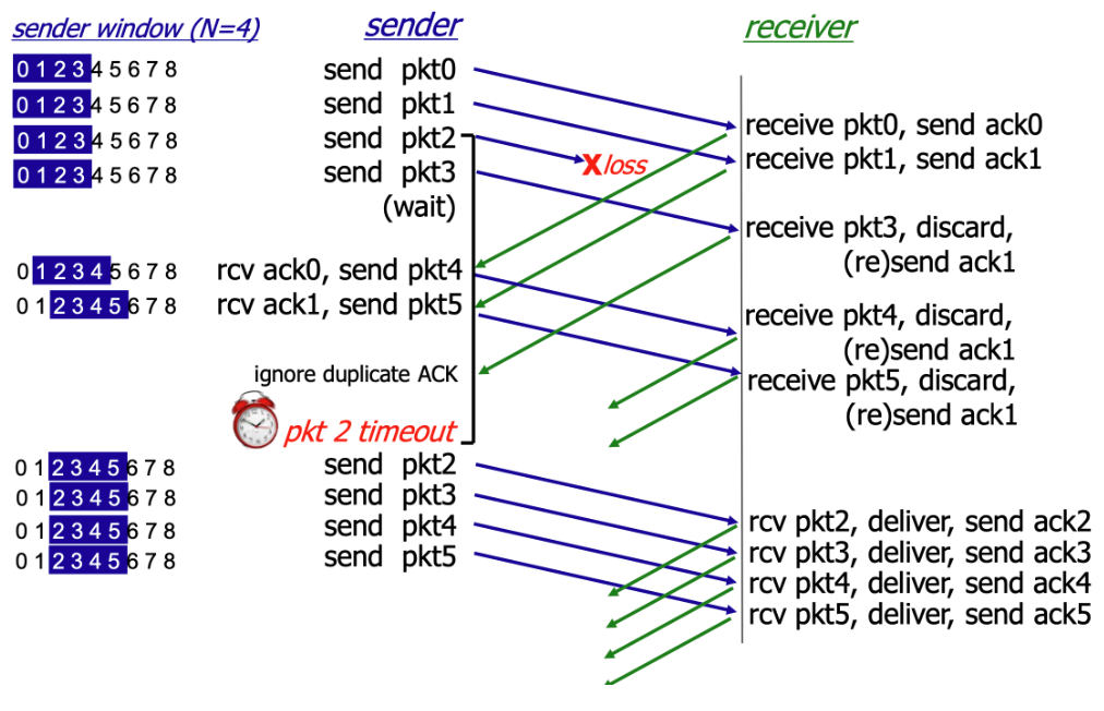
In simple terms, the sender transmits packets in order, and the receiver receives packets in order. If the receiver does not receive a packet, it discards any out-of-order packets and resends the acknowledgment.
SR
SR (Selective Repeat) is another sliding-window-based ARQ strategy. SR is theoretically never worse than GBN and can be considered an optimized version of GBN.
The core idea of SR is: when a packet is lost, the sender only retransmits the lost packet, rather than retransmitting all packets after the lost one as GBN does.
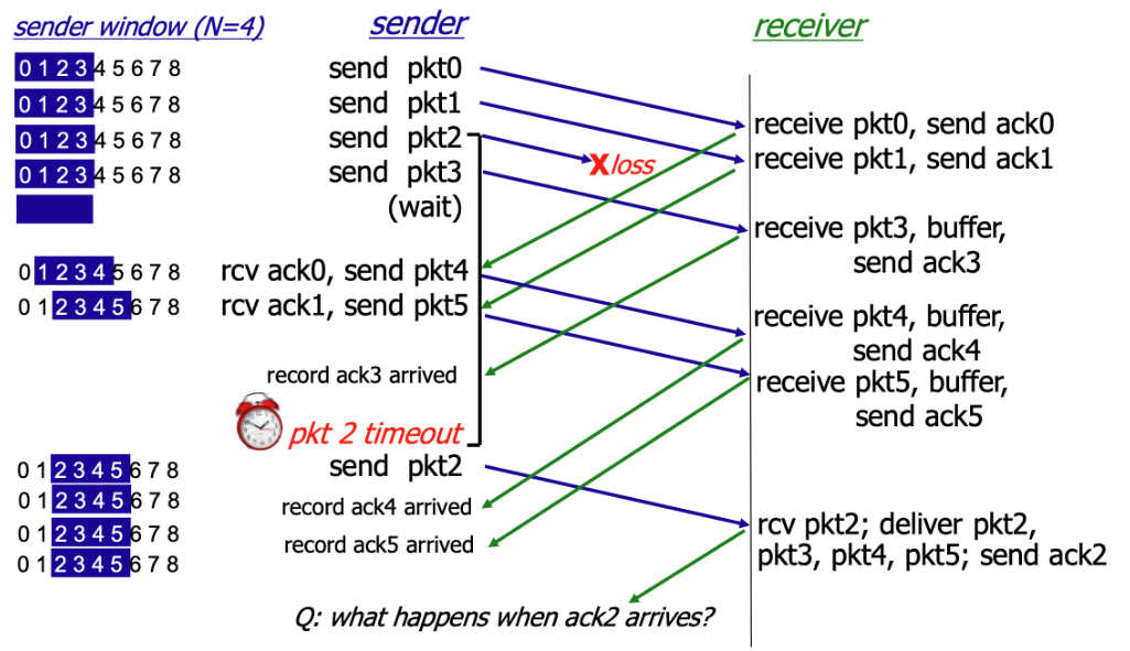
As shown, in the SR protocol, when the receiver does not receive pkt2, it continues to receive subsequent packets but does not formally accept them — instead, it buffers them. When the sender times out without receiving ack2, it retransmits pkt2. Upon receiving it, the receiver formally accepts pkt2 along with the buffered packets and sends ack2.
To ensure the reliability of the SR protocol, the window size \(N\) must satisfy the following condition:
This constraint is also known as the "SR dilemma." The fundamental reason is that when the sequence number space is insufficient, the receiver cannot distinguish whether a received packet is a retransmission of a lost packet from the current round or a new packet from the next round carrying the same sequence number.
3.3 Congestion Control
Congestion control is a mechanism unique to TCP, designed to protect the entire Internet from collapse. GBN and SR implement TCP's transmission reliability, but without congestion control, every sender would transmit data at maximum speed. When network traffic exceeds router processing capacity, all routers would start dropping packets, leading to congestion collapse. Congestion control exists to prevent this.
Congestion control employs the following mechanisms to prevent network congestion collapse:
- Congestion Window (CWND)
- Slow Start
- Congestion Avoidance
- Fast Retransmit
- Fast Recovery
Congestion control is like managing a busy highway (the network) — the goal is to let as many cars (packets) through as possible while preventing a traffic gridlock (congestion collapse). CWND is the maximum amount of data the sender can transmit into the network before receiving an ACK from the receiver.
The Receive Window (RWND) is a flow control mechanism that limits the receiver's capacity.
The actual amount of data the sender can transmit is limited by the minimum of CWND and RWND:
In general, however, CWND is the primary factor limiting the sending rate. Therefore, congestion control mainly targets CWND. We will study two congestion control methods: MIMD and AIMD.
MIMD
MIMD (Multiplicative Increase / Multiplicative Decrease) increases CWND exponentially during the increase phase:
And decreases it multiplicatively during the decrease phase (typically halving):
For example, during the increase phase, MIMD keeps doubling the allowed traffic; when congestion is detected, it keeps halving the allowed traffic.
Clearly, MIMD leads to severe oscillation and instability.
AIMD
AIMD (Additive Increase / Multiplicative Decrease) sacrifices the speed of MIMD but gains stability. Since network stability is more important, TCP/QUIC congestion control almost universally adopts AIMD.
During the increase phase, AIMD increases CWND linearly at a slow rate:
When congestion is detected, the decrease mechanism is the same as MIMD — typically halving — to quickly relieve pressure and prevent congestion from worsening:
AIMD is relatively fair, preventing the share gap between two flows from growing too rapidly, thereby allowing all flows to converge toward a fair share of bandwidth.
3.4 UDP
UDP (User Datagram Protocol) operates in a manner diametrically opposed to TCP. It is a connectionless, unreliable transport protocol, making its transmission process very simple and fast:
UDP requires no three-way handshake to establish a connection, no four-way teardown, no sequence numbers, acknowledgment numbers, or retransmissions. It simply transmits without concern for whether transmission succeeds.
The UDP header is very small and fixed — typically only 8 bytes — making its overhead extremely low:
- Source Port Number: 2 bytes.
- Destination Port Number: 2 bytes.
- UDP Length: 2 bytes (total length of the UDP header and data).
- UDP Checksum: 2 bytes (used to detect datagram corruption).
For example, DNS is a classic UDP application. When a device sends a query to a DNS server requesting the IP address corresponding to a domain name, the DNS server simply returns a UDP datagram containing the IP address. The client starts a timer when sending the request; if the timer expires without a response, the client resends the request. The entire process involves no connection or negotiation — only the client's request and the server's response.
3.5 QUIC
QUIC (Quick UDP Internet Connections) is a next-generation transport layer protocol proposed by Google and later standardized by the IETF, designed to replace the traditional TCP + TLS + HTTP/2 combination.
It runs on top of UDP but provides stronger performance, flexibility, and security than TCP. Because it uses UDP, QUIC does not require the traditional TCP three-way handshake or four-way teardown, instead adopting entirely new handshake and retransmission mechanisms.
HTTP/3 runs on top of the QUIC protocol. It is important to note that HTTP/3 mandates the use of TLS encryption at the lower layers, so HTTP/3 is always secure. However, terminologically, HTTP and HTTPS must still be distinguished: HTTPS is the general term for secure transmission, while HTTP (whether HTTP/1.1, HTTP/2, or HTTP/3) is the application layer protocol that defines data transmission formats and rules.
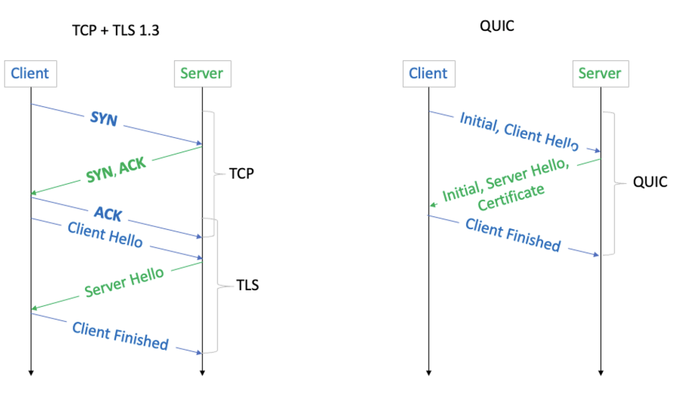
As shown in the diagram above, QUIC saves 1 RTT compared to TCP + TLS 1.3.
Ch.4 Internet Layer
TCP/IP has four layers in total, and the Internet layer corresponds to the Network layer in some textbooks. For convenience, in this chapter, "Internet layer," "network layer," and "internetwork layer" all refer to the same thing.
The network layer is primarily responsible for delivering packets from the source host to the destination host. Its core topics include IP, routing, and forwarding.
4.1 IP
Let us start with IP. At the beginning of these notes, we used the analogy of a large envelope. When we deliver the envelope from inside the neighborhood to the neighborhood gate, the gate guard needs to plan a route based on the final destination — and that final destination is determined by the Internet IP address.
IP (Internet Protocol) is the most important and fundamental protocol at the network layer. It provides an unreliable, connectionless datagram service. Important notes:
- The "Internet" in IP does not refer to the Internet as we commonly know it, but rather to inter-networking. Therefore, IP addresses like 192.168.0.1 are also used within LANs.
- The unreliable, connectionless datagram service means that the IP protocol itself does not provide error correction, packet retransmission, or order guarantees. These reliability requirements are implemented in the upper-layer TCP protocol.
However, when we generally refer to IP, we mean Internet IP. On the Internet, IP addresses are unique.
Related to IP are the ARP protocol (which resolves network layer IP addresses to data link layer MAC addresses) and the ICMP protocol (which reports network errors and device status information).
The complete IP protocol includes IP addresses and IP datagrams. An IP datagram is the packaged letter — the large envelope from our earlier analogy. The address written on the envelope is the IP address.
IP Datagram
The IP datagram is the basic unit of transmission at the network layer, consisting of a header and a data payload.
IPv4 Addresses
An IP address is a numerical label used to uniquely identify each host or network interface connected to a network. Currently, the Internet primarily uses two IP address versions: IPv4 and IPv6.
Let us first look at the most commonly used IPv4.
An IPv4 address typically consists of four numbers, such as 192.168.1.10, but these four numbers do not have fixed, independent meanings — together they form a 32-bit address.
The \(32\)-bit binary structure of an IPv4 address is the foundation of hierarchical addressing:
Where:
- The Network ID identifies the network or subnet to which the device is connected. Routers rely primarily on this network ID to determine where to forward packets across the Internet.
- The Host ID identifies a specific device within that network. Once a packet reaches the correct network, the data link layer and network layer use this host ID (in conjunction with the MAC address) to deliver the packet to the correct device.
Since the boundary between the network ID and host ID is variable, we need the subnet mask to determine how many of the 32 bits are the network ID and how many are the host ID:
- Bits set to 1 in the subnet mask correspond to the network ID portion of the IP address.
- Bits set to 0 in the subnet mask correspond to the host ID portion of the IP address.
In other words, knowing the IP address alone is not enough — we must also know the subnet mask to determine the network ID and host ID.
For example, 128.124.2.44 could be:
- A host in network \(128.0.0.0/8\) (Class A network).
- A host in network \(128.124.0.0/16\) (Class B network).
- A host in network \(128.124.2.0/24\) (Class C network).
This is CIDR notation: IP address / network prefix length. The Class A, B, and C network classifications noted above were the pre-CIDR classification scheme, which wasted large numbers of IPv4 addresses. CIDR temporarily solved the IP address shortage by using variable-length network prefixes.
Only when an IP address is combined with a subnet mask does it become a complete, usable address.
Subnet masks do not appear out of thin air — they exist in two key locations:
- On computers, phones, or servers when configuring IP addresses, the operating system automatically obtains the subnet mask via DHCP, or the user can configure it manually. The terminal uses this subnet mask to calculate the local network address, thereby knowing which IP addresses are neighbors (reachable directly via the ARP protocol) and which are remote (requiring forwarding to the default gateway).
- In router routing tables — all routers on the Internet store routing entries that include subnet masks (expressed as CIDR prefix lengths). Routing entries contain the destination network address, prefix length, next-hop address, etc. Details will be covered in the routing section.
In short, a router determines whether two hosts are on the same subnet by performing an AND operation on each host's IP address with the subnet mask. If the two results (the network address) are identical, the hosts are on the same subnet.
IPv6 Addresses
As mentioned above, CIDR notation was invented to address the IP address shortage. However, no one anticipated that the Internet would grow to today's enormous scale: IPv4 addresses have also run out.
With an upper limit of only a few billion addresses, IPv4 is clearly insufficient in an era where nearly everyone owns a smartphone. As early as 2011, IANA allocated the last IPv4 address block. Today, obtaining new IPv4 address blocks requires purchasing them from existing holders. MIT made a windfall from holding a large number of IPv4 addresses.
To solve this problem, IPv6 was proposed. Although IPv6 adoption has been very slow, it will gradually become the primary network layer, while IPv4 will slowly become a permanent compatibility layer. In China, the three major telecom operators have fully launched IPv6. When mobile phones access the Internet via cellular data, IPv6 is prioritized — IPv4 is used as a fallback only when the target service does not support IPv6.
4.2 Routing
When sending a packet, the computer first uses the local subnet mask to determine whether the destination IP is a local address or a remote host. If it is a local address, the MAC address of the local host is found directly via the ARP protocol, and no routing is needed. If it is a remote host, the packet must be sent to the gateway, and Internet routing begins.
Functionally, a router performs two tasks:
- Routing
- Forwarding
Routing is a long-term, ongoing decision-making process that determines the complete path from source to destination. It is performed through routing protocols such as OSPF and BGP. Routers continuously exchange information with other routers, compute optimal paths, and build and maintain routing tables.
Forwarding is an instantaneous, real-time action. Based on the already-established routing table, the router determines the next hop for the current packet and sends it out through the correct interface. The route lookup (IP Lookup) queries the routing table based on the longest prefix match principle.
OSPF
OSPF (Open Shortest Path First) is one of the most popular Interior Gateway Protocols (IGP), used for routing within a single Autonomous System (AS) — for example, within a large enterprise or ISP network.
BGP
BGP (Border Gateway Protocol) is the core routing protocol of the Internet. It is the only Exterior Gateway Protocol (EGP), used to exchange routing information between different Autonomous Systems (AS) — for example, between different ISPs.
4.3 Forwarding
Forwarding is the router's real-time execution action. Its core lies in IP Lookup — finding the unique exit from the routing table based on the destination IP address.
When a packet arrives at a router:
- Read the destination IP: The router examines the destination IP address in the IP packet header.
- Query the routing table: The router matches the destination IP address against the CIDR prefixes of all entries in the routing table.
- Follow the principle: The router strictly follows the Longest Prefix Match (LPM) principle.
The LPM principle is the key mechanism by which routers handle variable-length subnet masks and route aggregation:
- Principle: If a destination IP address matches multiple prefixes in the routing table, the router must select the route with the longest prefix length (i.e., the most specific subnet mask).
For example, suppose our destination IP is 10.1.1.15, with the following binary representation:
We then look up the network prefixes in the routing table. The routing table does not store individual host IP addresses; instead, it stores network blocks.
For example, the routing table might contain the following entries:
- \(10.0.0.0/8\)
- \(10.1.0.0/16\)
- \(10.1.1.0/24\)
These entries represent different ranges:
- \(10.0.0.0/8\) represents all addresses from \(10.0.0.0\) to \(10.255.255.255\).
- \(10.1.0.0/16\) represents all addresses from \(10.1.0.0\) to \(10.1.255.255\).
- \(10.1.1.0/24\) represents all addresses from \(10.1.1.0\) to \(10.1.1.255\).
We can see that 10.1.1.5 falls within all three ranges. To ensure the packet reaches the most precise destination, the router must select the smallest network block containing that IP address — the one with the longest prefix, \(/24\).
Once LPM determines the next-hop IP address and outbound port, the router performs forwarding:
- Decrement TTL by 1: The TTL (Time to Live) field in the IP header is decremented by 1. If TTL reaches \(0\), the packet is dropped, and an ICMP error message is sent to the source host.
- Data link layer encapsulation: The router re-encapsulates the packet with a new data link layer header.
- Determine the next hop's MAC address (typically obtained via ARP).
- The source MAC address is the MAC address of the router's outbound interface.
- Send: The new frame is sent through the designated outbound port to the next-hop device.
Ch.5 Link Layer
In some textbooks, the Link layer is divided into the Data Link layer and the Physical layer. In the TCP/IP model, the Link layer encompasses both.
Topics include:
Frame, error checking, LAN, ARP, MAC addresses
MAC protocols, CSMA/CD, CSMA/CA
Ethernet, PPP, HDLC, Wi-Fi
Not yet organized — will study if the need arises.
Ch.6 Network Security
Network security topics include: firewalls, IDS/IPS, asymmetric encryption, certificates, TLS
DDoS attacks, ARP spoofing, cross-site attacks
Zero-trust security architecture, etc.
Link Layer Supplement
Ethernet Frame Structure
| Preamble(8B) | Dest MAC(6B) | Src MAC(6B) | Type(2B) | Data(46-1500B) | FCS(4B) |
MAC Address
A 48-bit hardware address (e.g., AA:BB:CC:DD:EE:FF), where the first 24 bits are the vendor identifier (OUI).
ARP Protocol
Mapping from IP address to MAC address: 1. Broadcast an ARP request: "Who has IP 192.168.1.1?" 2. The target host replies with its MAC address via unicast 3. The result is cached in the ARP table
Switch vs. Router
| Device | Layer | Forwarding Basis | Broadcast Domain |
|---|---|---|---|
| Switch | L2 | MAC address | Same VLAN |
| Router | L3 | IP address | Isolates broadcasts |
Network Security Supplement
TLS/SSL
Transport Layer Security protocol, providing encryption, authentication, and integrity:
TLS 1.3 Handshake (1-RTT): 1. Client Hello (supported cipher suites, key share) 2. Server Hello (selected cipher suite, certificate, key share) 3. Both sides compute the session key and begin encrypted communication
Common Attacks
| Attack | Mechanism | Defense |
|---|---|---|
| ARP Spoofing | Forged ARP replies | Static ARP, DHCP snooping |
| DNS Hijacking | Tampered DNS responses | DNSSEC |
| DDoS | Overwhelming target with massive traffic | CDN, traffic scrubbing |
| Man-in-the-Middle | Intercepting and altering communications | TLS, certificate verification |
HTTP/2 and HTTP/3
HTTP/2
- Multiplexing: Multiple parallel requests/responses over a single connection
- Header Compression: HPACK algorithm
- Server Push: Proactively push related resources
- Binary Framing: Replaces the text format of HTTP/1.1
HTTP/3
- Based on the QUIC protocol (reliable transport over UDP)
- 0-RTT connection establishment
- Eliminates head-of-line blocking (each stream is independent)
- Built-in encryption (TLS 1.3 integrated into QUIC)
See Application Layer Protocols for more details on HTTP/DNS/WebSocket.
Relations to Other Topics
- TCP/IP Protocol Stack drills into packet formats, state machines, and transport details inside the layered communication model.
- Application Layer Protocols continues with HTTP, DNS, WebSocket, and other software-facing interfaces.
- Operating Systems explains how sockets, interrupts, buffers, and I/O multiplexing support network programming.
- Distributed Systems shows how latency, failure, retry behavior, and consistency become first-class design constraints.
References
- James F. Kurose and Keith W. Ross. Computer Networking: A Top-Down Approach. Pearson.
- Andrew S. Tanenbaum and David J. Wetherall. Computer Networks. Pearson.
- W. Richard Stevens. TCP/IP Illustrated, Volume 1. Addison-Wesley.